The Yamaha TX7 IS the famous DX7 in the form of a tabletop
strange shaped box.
It’s build like a tank and has the same synth engine like
the DX7 minus the keyboard.
The only (not actually real) drawback is the panel editing
which is minimal, but that was not a design flaw by Yamaha because the TX7 was
designed to work in conjunction with the DX7 as an expander, and all editing
would be done through the DX7’s controls.
But of course there are some excellent editors/librarians
out there to facilitate patch editing like the free DEXED virtual FM synth
which is also a librarian for the DX7/TX7 and the MIDIQUEST librarian software
(expensive but totally worth it), just to name two of them.
I always craved for the DX7 vibe since I was at school, but
could never get my hands on one (no money L ). Recently I finally purchased one used at a fairly
good price and started to explore the complicated nature of FM synthesis.
I already have an SY85 workstation (excellent synth by the
way and so easy to use), and I noticed that at my dark studio the TX7 showed
nothing!! Really? Nope, just the LCD display was non-lit from the factory..
What a bummer! So I decided to make a match of my SY85 green
LCD and the TX7.
So I prepared a detailed guide how to replace the stock
Non-lit display of the TX7 with a modern LCD module that has a backlight.
So here it goes:
YAMAHA
TX7 LCD DISPLAY REPLACEMENT GUIDE
1.)
LCD IDENTIFICATION & SELECTION :
The TX7 uses a 16X1
character LCD display, which means 1-line with 16-characters.
The Optrex stock display has only 14-pins (since there is no
backlight) but the modern modules with a backlight have 2 more pins (15 &
16) to give power to the backlight.
In order to find a replacement LCD display you have to:
i. Compare the external dimensions of the stock and the new module. Don’t worry
about the thickness now, new modules are usually thicker. We will accommodate
this later when installing the new LCD module.
ii. Compare the PINOUT scheme of the two modules so that they match. Please note that
all modern displays have these 2 extra pins for the LED backlight, just make
sure you match the other 14 pins.
The stock Optrex display pinout is shown in the service manual

The LCD display I used for my TX7 is this:
And the pinout
comparison is this :

So, it is a match !
All we have now to do is to find a power source in the TX7's
PCBs to draw power for the backlight (to connect the pins 15 & 16 ).
There is a photo of the display I used:

But first, let’s open-up the synth and start working :
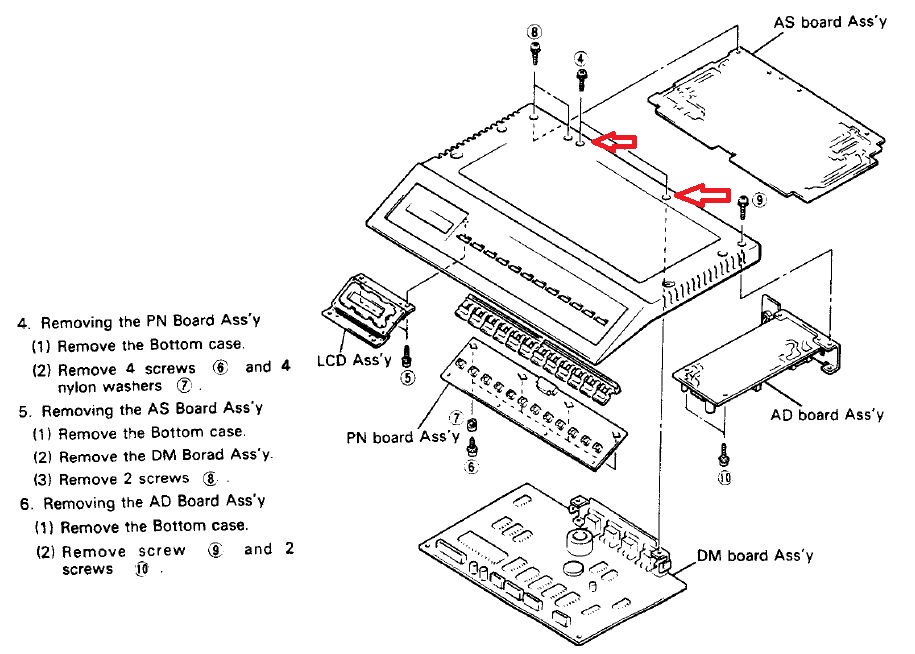
2.) TX7 DISASSEMBLY :
2.1 First remove the 2 screws shown in the
following pic with arrows. These screws hold the main board of the TX7 in
place. You need to do this, because later you need to remove it to gain access
to the power supply socket that will drive the backlight of the new display.

This is the page from the service manual that has the
instructions for complete disassembly.
2.2 Place the TX7 upside down on a soft surface
in order to protect it from scratches.
Remove the screws of the bottom cover as shown in the
following photo:

Instructions are also given in the service manual :

Then , remove the bottom cover from the synth . This is what
you see inside:

On the left is the
power supply . In the front-left you can
see the front panel board and on the
front-right the LCD display assembly.
3.) LCD DISPLAY REPLACEMENT STEPS :
3.1 Remove
the 14-pin connector from the LCD module

3.2 Remove the 2 screws that hold the LCD
display on the TX7’s chassis


This is the stock LCD display (Optrex DMC 16117 UL) which, as you can see, has only 14-pins
meanwhile modern display modules have 2 additional pins (15 & 16) to power
the LED backlight.

3.3 The metal brackets are attached to the
module with 4 plastic rivets.

These need to be removed in order to re-use them with the
metal brackets for the new backlit display.
Take care because the
plastic rivets are small and delicate! 😅
In order to remove the plastic rivets, push the center of
the back end of the rivet with a small screwdriver or pencil.
Now you have the metal bracket assembly READY for use with
the new display.
3.4 LED
POWER :
Before we move to the installation of the new LCD display, let’s
find the power for the backlight:
As we already have removed the 2 screws that hold the main
PCB in place (in step 2.1) , carefully tilt the PCB and place it gently as
shown in the photo below. You do not need to remove the ribbon cables
for this task.

In this same photo, we can see the power supply of the TX7
(on the left). The RED arrow shows the 4-pin socket to
which we will connect the jumper cables to get the +5Volt that is needed to power the LED backlight of
the new display.
You can see that one pin says +5Volt and the other
adjacent pin is the GND (ground). Yamaha has
those clearly labeled, so it is really hard to miss it.
>> ATTENTION
must be paid NOT to connect to the 2 other pins
of the same connector that read +15Volt (see photo below), or you will say BYE-BYE to your new
display !!

Then find or make 2 jumper cables to make the necessary
connections.
So, I made two 20 cm long jumper cables. I used cabling from an old computer that already had the terminal housings fitted on one side.
In the two photos below,
- the RED
cable is connectedone end to Pin 15 of the display and the other end to
+5Volt (TX7 socket) ,
- and the BLACK has one end to pin 16
(GND) of the display and the other end to GND (TX7 socket).


Again, ALWAYS DOUBLECHECK
THE PINOUT SCHEME OF THE NEW DISPLAY.
In my selected display PIN 15 is power and pin
16 is GND, other brand displays may differ.
3.5 New
display assembly :
For the new display to fit into the TX7, we shall use the
metal brackets . Since the new display is thicker, I chose to place the metal
brackets in front of the display PCB (photo below).
In order to avoid damaging the copper traces of the display’s board, some insulating tape should be
placed between the display
and the metal bracket. I used pieces of rubber tape (see photo below).

3.6 Module
Installation
Since the new display is thicker, some ~2 mm washers also need to be placed under the metal bracket, in
order to align the display with the outer glass and bezel of the TX7.


Then use the 2 screws to mount the display, but do NOT overtighten them. Just enough to
keep it in place.
And now, you will see that our new display is perfectly snug with the TX7 case!
Finally :
- connect
the 14-pin Yamaha connector to the display

- and connect the
power cables one end to pins 15 and 16 of the display and other end to the
power supply socket of the synth.
Then, carefully place the main PCB back in its position, and
we are ready to test and close the TX7!

3.7 TESTING :
>> Temporarily
put the bottom cover to the TX7 (2 screws in the middle are adequate) and
carefully turn it again upside up.
>> Connect
the power plug to your wall’s 220V source and power the TX7 on…

Now we are talking !!!
4.) TX7 RE-ASSEMBLY :
>> Power-OFF the TX7 and remove the
power-plug from the 220v house wall source.
>> Now put all the screws you removed back in their respective
place and you are good to go !!!
There you have it ! A nice green bright display !


I hope this guide is simple and clear and helpful for you boys and girls who want to
Light Up The Night !!!
>> For your convenience, you can download this guide as .pdf document from here .
Greetings!!!
Thank you :-)
ReplyDeleteYou are welcome. :)
ReplyDeleteI also got my display from "Buydisplay.com"
ReplyDeleteBut I found that the lighting was too bright and I disconnected/cut the 5v power supply of the display and soldered in an 820R ohm resistor, 510R to 1K is very good to get a good light! I also increased the 56R Ohm resistor to 450R Ohm to increase the contrast, so the dark blocks in the display have disappeared and the writing is clearer! The 56R Ohm resistor is on the circuit board where "CONT" is written, CONT stands for contrast, there are two resistors next to each other, the 56 Ohm and one 18K resistor! See also wiring diagram. I got this idea from another forum, there is also a manual for it, but the one there installs a "winstar display" but the changes can of course also be made for this display. Everything is great for me! thanks